|
|
 |
|
 02-09-2007, 11:41 PM
|
#1
|
|
I, Vettezuki
Join Date: Feb 2006
Posts: 14,754
|
 Old Shark Gets New Teeth
Finally, after nearly a year of acquiring parts and researching, the conversion of my 82' to an LS is underway. I'll update this thread as I go and hopefully it'll be useful to anyone else considering this conversion in the future.
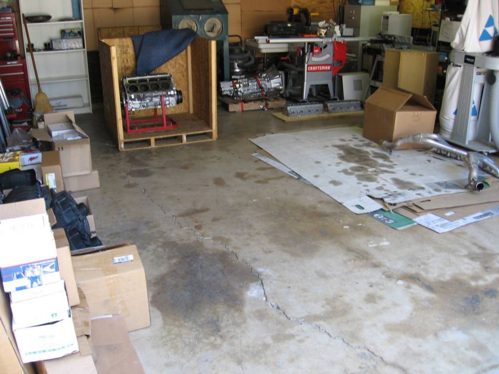
Here's the short block, Heads and Trans before loading up.
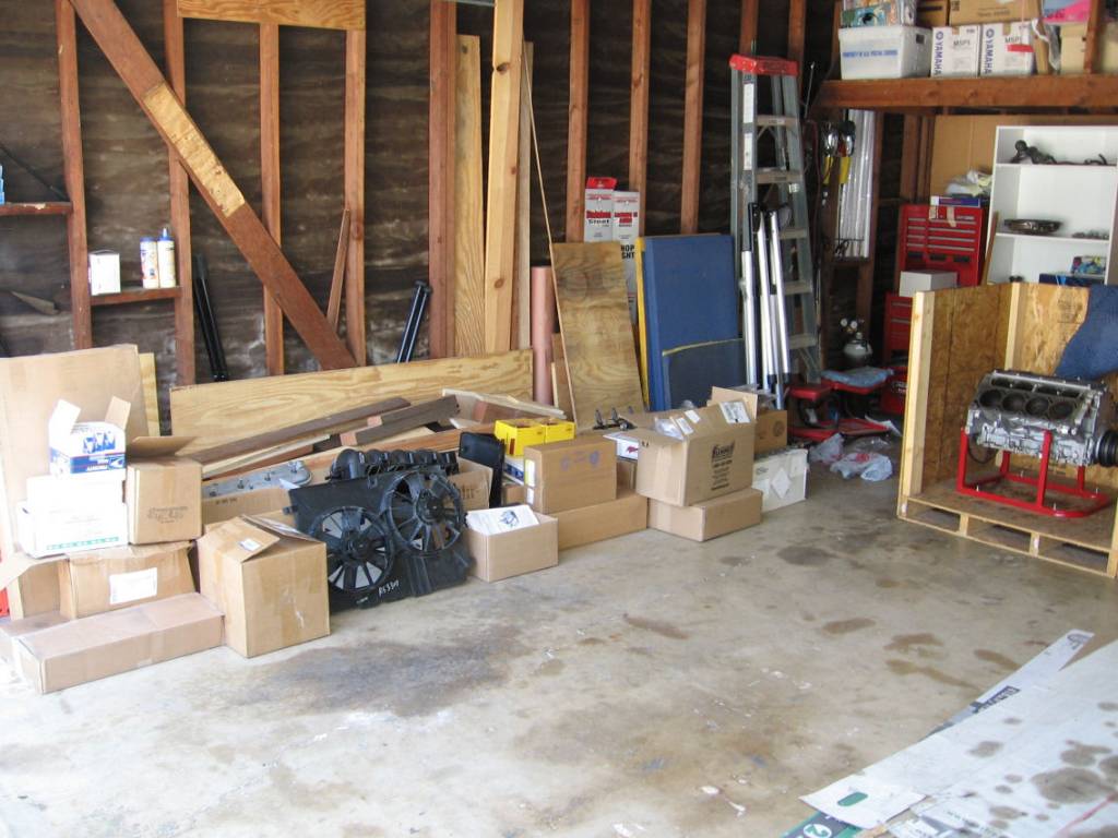
A pile of miscellaneous parts and accessories.
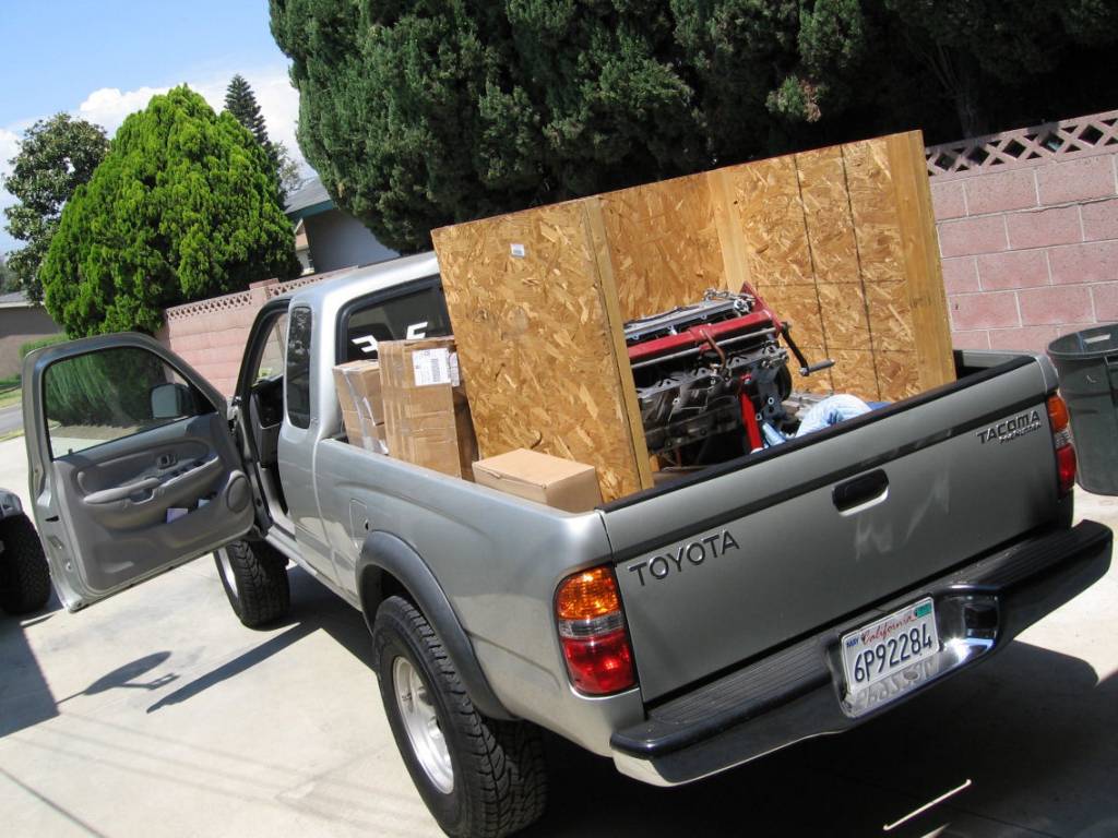
A truck loaded with all the goodies for transport to conversion location.
Last edited by Vettezuki : 02-11-2007 at 07:38 PM.
|
|
|

|
 02-09-2007, 11:49 PM
|
#2
|
|
I, Vettezuki
Join Date: Feb 2006
Posts: 14,754
|
 Just a Couple Gotchas
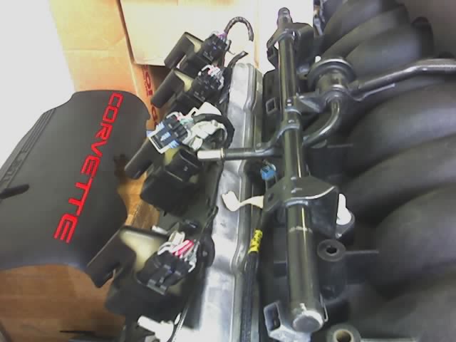
So here's some examples of the problems I ran into. I bought truck coil packs with the mistaken understanding they would work for my application. Technically, the coils would work, and some builders say the truck coil packs are slightly superior because of higher heat tolerance. However, they most certainly can not be mounted in conjunction with the F/Y body fuel rails. See below. Note how the fuel rail connection points directly into the coil pack connector. I guess guys who use the truck packs must be using after market fuel rails.
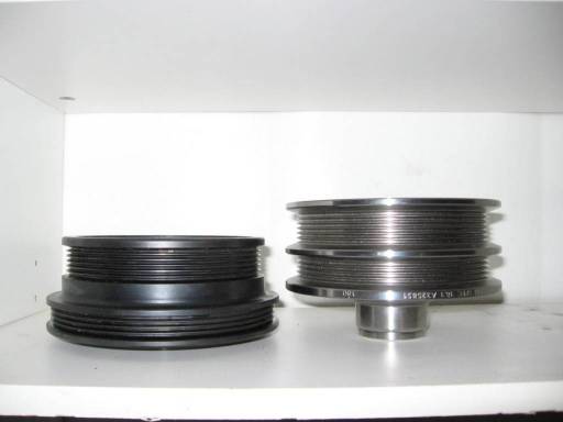
Next, note the rather substantial difference between F and Y body balancers. The Y body on the left is much tighter to the block. I recommend the F body because it gives a little more clearance away from the block, which will come in handy for mounting an R4 A/C compressor in front of the passenger side head. You cannot use the stock A/C compressor because it completey interferes with C3 control arms.
Other gotchas.
The LS1 intake from a Y body does not have the threaded inserts to mount the throttle cable bracket, which is necessarry for our C3s . . . unless you want to try and get a fly by wire setup to work. This is not such a huge problem since I'll take the opportunity to upgrade to an LS6 intake. Note, there is NO smog legal intake other than stock in CA. BBK is working on getting an E.O.#, but they don't yet have one.
The TPIS headers I got with the motor came from a Y body as well. Regrettably they tie together underneath the bellhousing area and go straight back. On the Y body, there is space because there is much more clearance by the torque tube as the transmission is in the rear. On my F body like setup, the bell housing is much larger as the transmission is in the front and therefore no room.
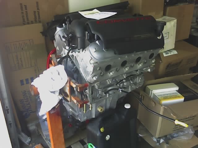
Finally, the motor as of a few days ago:
Last edited by Vettezuki : 02-11-2007 at 02:39 AM.
|
|
|

|
 02-10-2007, 12:05 AM
|
#3
|
|
I, Vettezuki
Join Date: Feb 2006
Posts: 14,754
|
 Engine Photos
The motor is currently at my Uncle's machine shop. From next week they'll begin designing and making an A/C mounting bracket and modifying the waterpump. Here's some pics of its current state.
Here's the SLP F-Body Underdrive. When the A/C is finally installed, we'll probably run everything off of this one pully since it will line up better than trying to get it to run off the A/C pully.
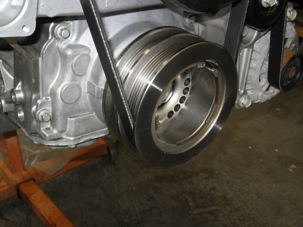
Here' you can see the heater pipes coming straight out of the waterpump. Unfortunately they go straight in to the control arms on a C3. We'll probably pull these pipes out, tap between them for bolting an adapter that will point back and up and seal with o-rings. That's the plan at the moment anyway.

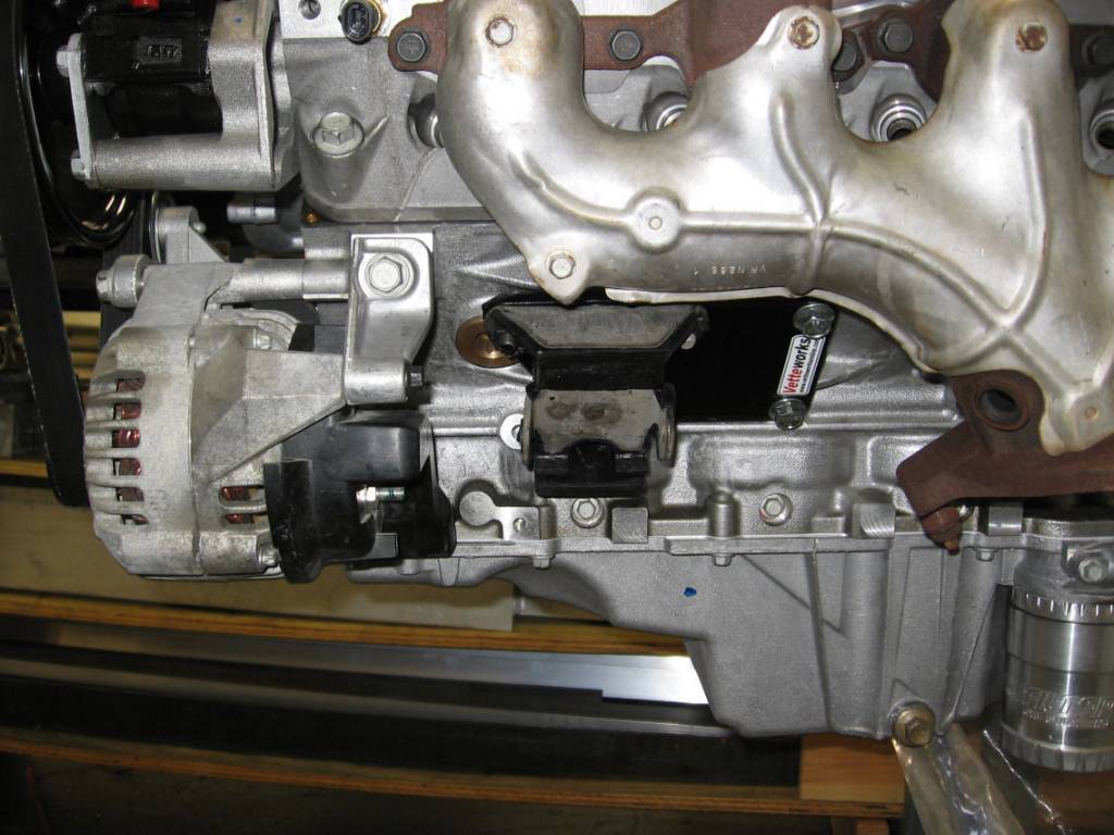
Under the manifold you can see the Vettworks adapter plate and stock motor mounts. This should make for a nice mounting position in the engine compartment. You can also see the world's most expensive oil filter . . . time will tell if that was worth while or not. Looks cool 
The ported truck throttle body that supposedly flows just over 1000 CFM. In conjunction with the LS6 intake, bigger cam and hi-flowing, hi-compression heads, this motor should make an honest 400 plus to the ground on a good tune and stock exhaust. We'll see 
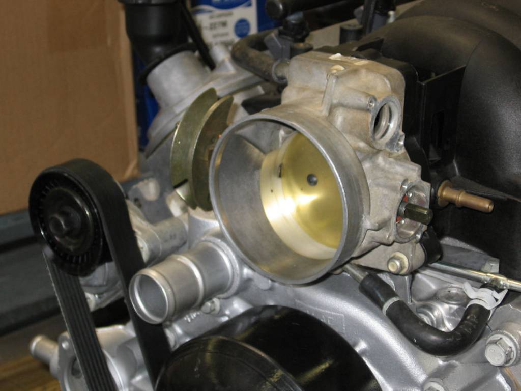
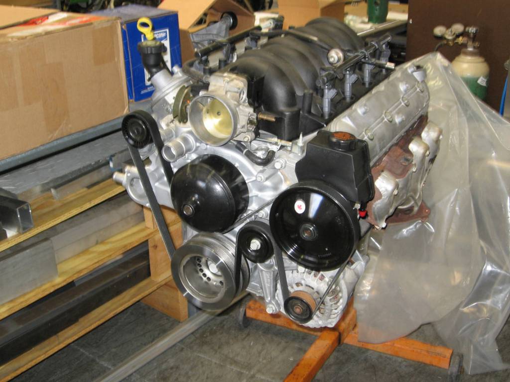
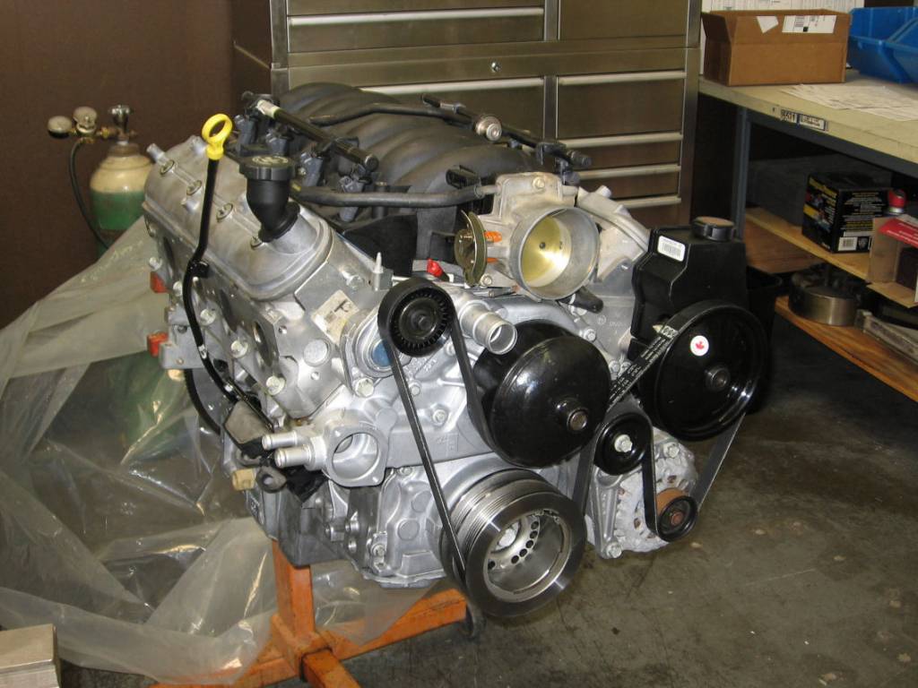
Some other angles of the motor. You can easily see the stock F-Body routing of the accessories. The A/C will go in the upper passenger side and most likely on a single serpentine. This will require relocating the tensioner which is presently mounted to the waterpump.
Last edited by Vettezuki : 02-14-2007 at 08:54 PM.
|
|
|

|
 02-10-2007, 12:14 AM
|
#4
|
|
I, Vettezuki
Join Date: Feb 2006
Posts: 14,754
|
 Motor Comes Out
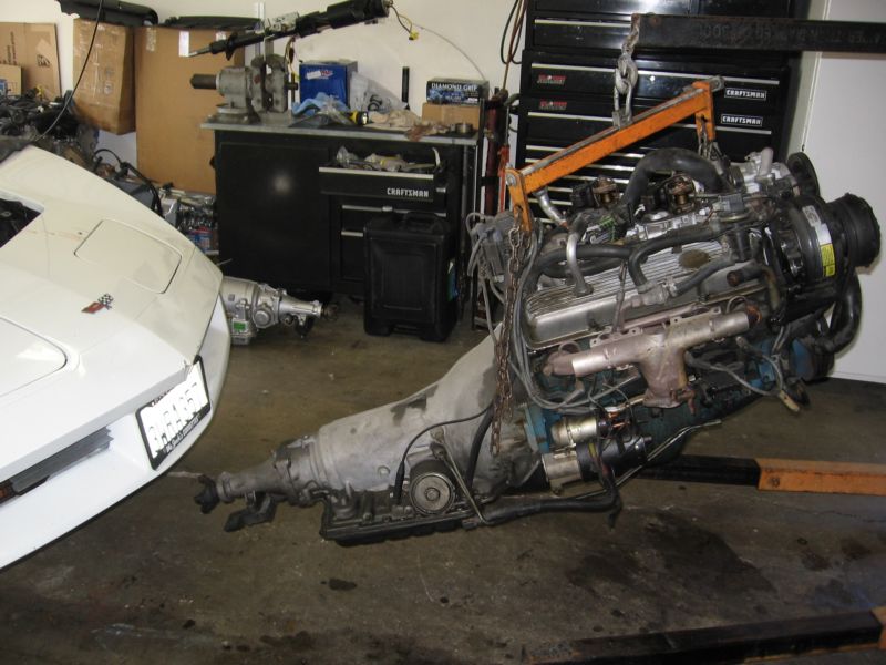
Finally, back to actual work. Today we removed the old lump.
Here it is up on stands, getting fluids drained and various connections removed:
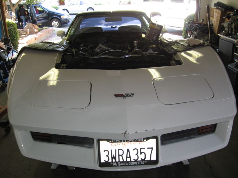
Side view of the L83 prior to removal:
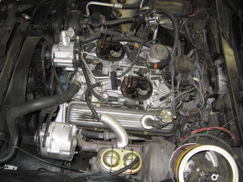
Top view from above cockpit . . . looks like something the Borg would make :laughing:
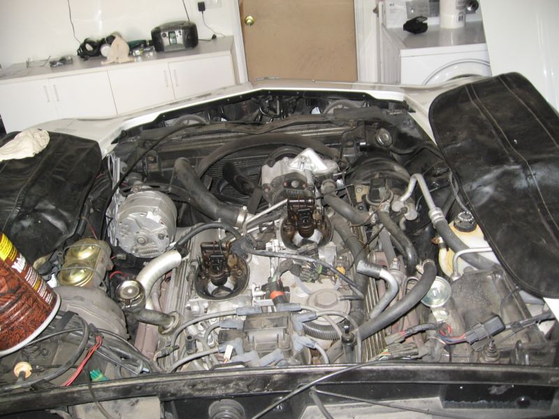
Removed. Actually, once connections were severed it came out in one piece pretty easily.
The empty engine bay. We'll clean her up good'n purty before installing the new motor and trans. Plus we'll use this time to install the new clutch/brake pedals, locate the ecm etc.
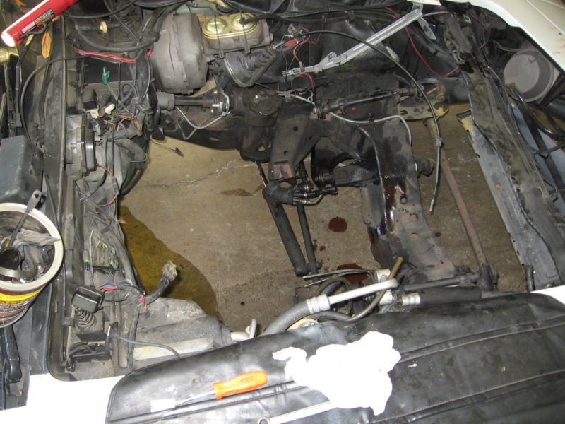
I'm hell bent on keeping A/C and to the greatest extent possible, stock locations for things I'm keeping. I'll be deleting the cruise control. We're thinking to locate the ecm about where the crusie control and maybe windshield wiper fluid bottle (never use that anyway). It's a nice discrete spot. A second possiblity is to exchange my harness for the longer run and piggy back with the sctock ecm and harness path, which is in the cabin. I kind of like keeping it shorter and all in the compartment as they are on modern cars.
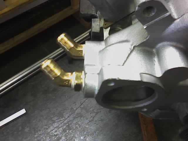
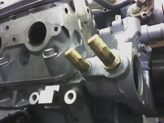
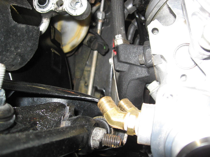
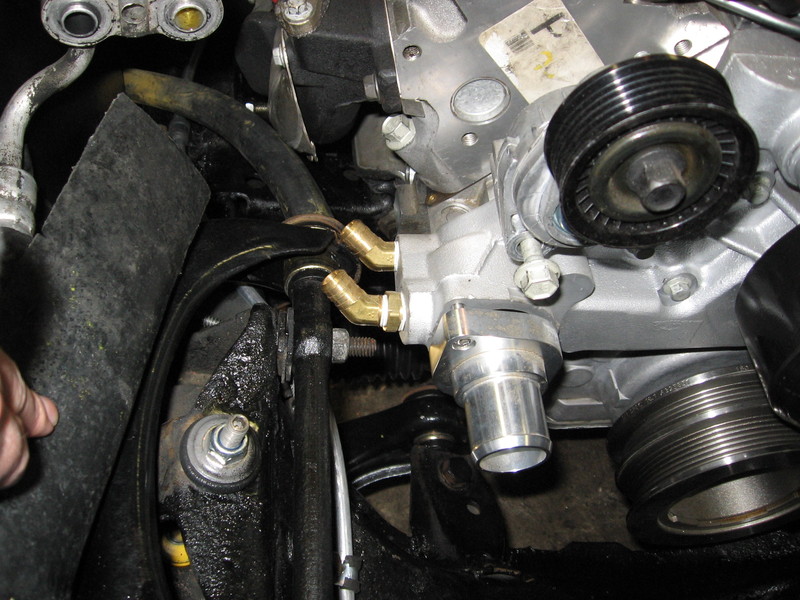
Also, one thing we did manage to do at my cousin's place was pull the stock heater pipes and replace with 45 degree brass fittings. I used a 1/2 -> 3/8 bushing and 3/8 on both the send and return. Since it is a closed and pressurized fluid system, 3/8 is the least common denominator for flow anyway so it makes no difference in function. Apparently having different sizes was just a keying mechanism so they would connect the send and return correctly on the assembly line. This should clear the control arm just fine and give a nice flowing shot to the heater core.
Until next time. :cheers:
Last edited by Vettezuki : 02-11-2007 at 08:04 PM.
|
|
|

|
 02-11-2007, 02:23 AM
|
#5
|
|
Resident Avatar Gambler
Join Date: Nov 2006
Posts: 5,997
|
The car looks awesome - it's going to be a beast when it's done... Not as quick as the minivan, but probably close....
|
|
|

|
 02-11-2007, 08:11 PM
|
#6
|
|
I, Vettezuki
Join Date: Feb 2006
Posts: 14,754
|
 It's been a while
Well, basically the delay is the result of a few things, but mainly the conversion from 700R4 to T56 (really just sorting the Master Cylinder).
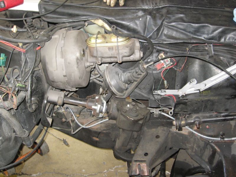
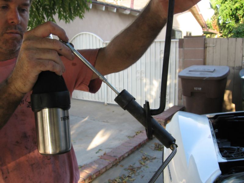
Originally I was just thinking o f using a new 4th Gen MC, but the angle is totally wrong. Eventually I ended up going with an 85 Chevy 1 ton, because curiously it is a direct bolt up to the C3 Firewall; however, I did have to modify the rod.
Here's the Camaro MC in the orientation it would be in the C3:
Here's the same MC in the orientation it needs to be in:
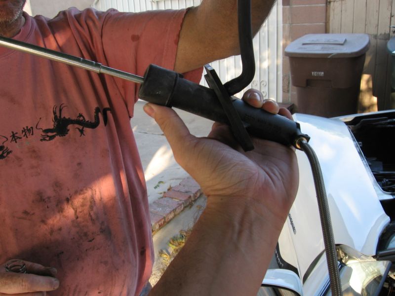
Here's the location where it slips through the firewall and links up to the clutch pedal.
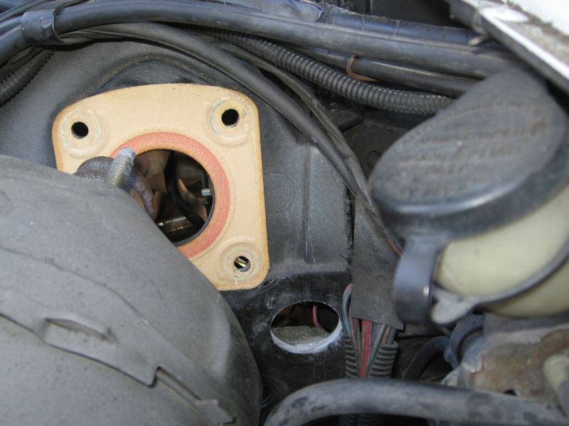
Here you can visualize a little better the problem with the 4th Gen MC. Supposedly Street and Performance makes and adapter that mounts to the firewall using the brake booster bolts. I decided to just go with the truck master.
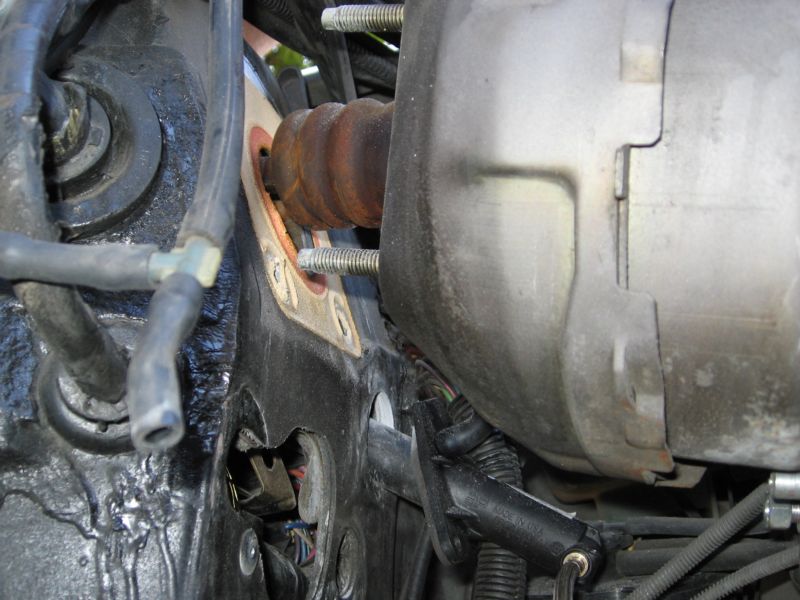
The down side of the truck master that I got from AutoZone is that it did not include the resevoire or hydraulic line (naturally). So I've had to run down a hydraulic line with the correct quick connect to the slave and will have the "Hose Man" make up the A/N fitting for the MC side. Remote resevoire is not such a big deal, just make sure the feed line is rated for hydraulic/brake fluid and not just any rubber.
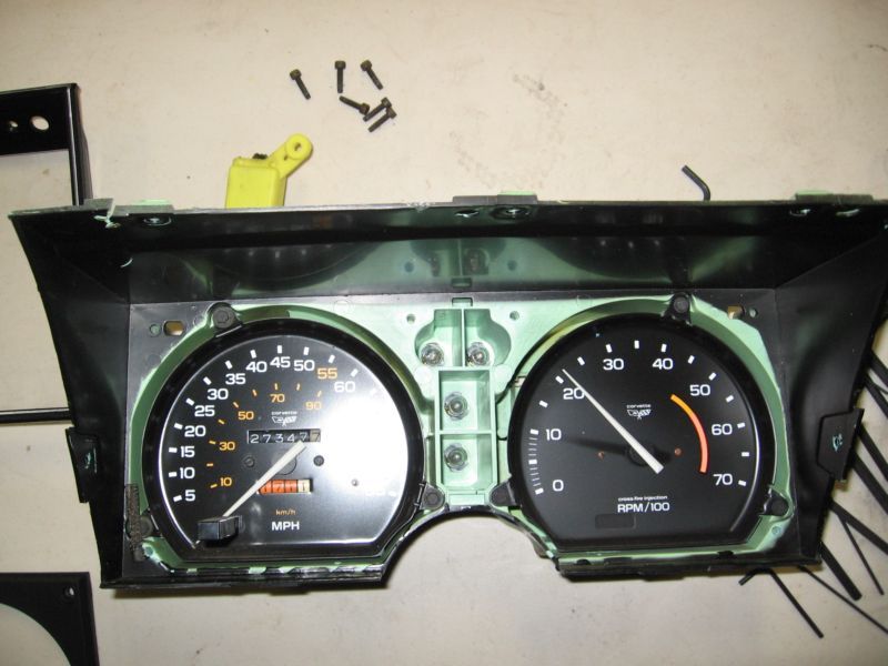
Next problem is the speedo and tac. On my 82' the Speedo is mechanical and the the Tac is electronic. While driving around with my speedo (safely) pegged to 85mph was amusing, it did get kind of old. So like a true dork I bought 5" 200mph AutoMeter gage. Looks great, and I thought there'd be plenty of space in the panel to massage it into place. . . no. However, making a new instrument panel isn't sooooo hard.
To start with, the depth is a bit wrong, plus I'd have to hack apart the inards of the stock panel, which is kind of a no no for me.
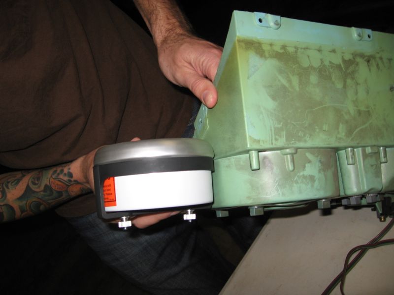
With face plate off:
[img][/img]
Not to worry, that's why god invented cardboard:
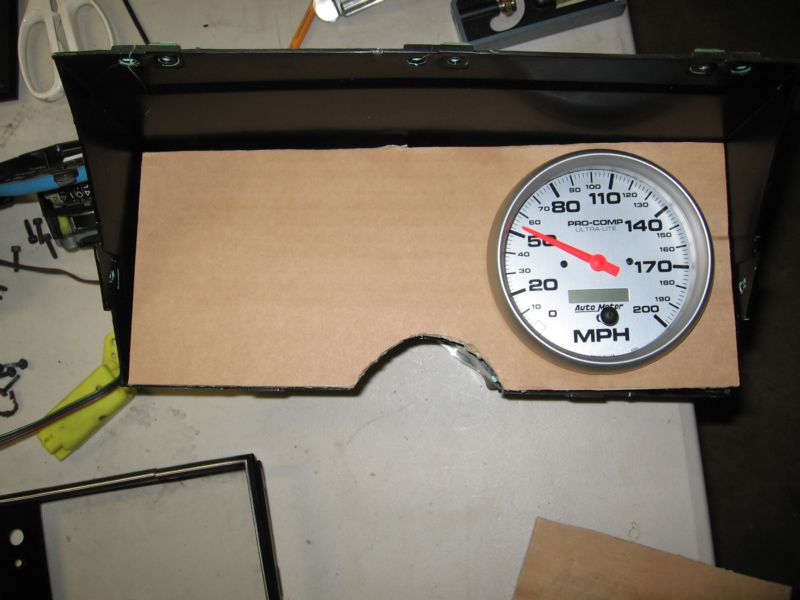
For mock up . . .
So I bought some ABS plastic, weld on 4 glue, hole saws and so on. Tomorrow night we'll build the new panel. It'll be good enough to last a couple years before getting to the full-tilt new interior.
Last edited by Vettezuki : 02-14-2007 at 09:02 PM.
|
|
|

|
 02-11-2007, 08:42 PM
|
#7
|
|
I, Vettezuki
Join Date: Feb 2006
Posts: 14,754
|
 Instrument Panel
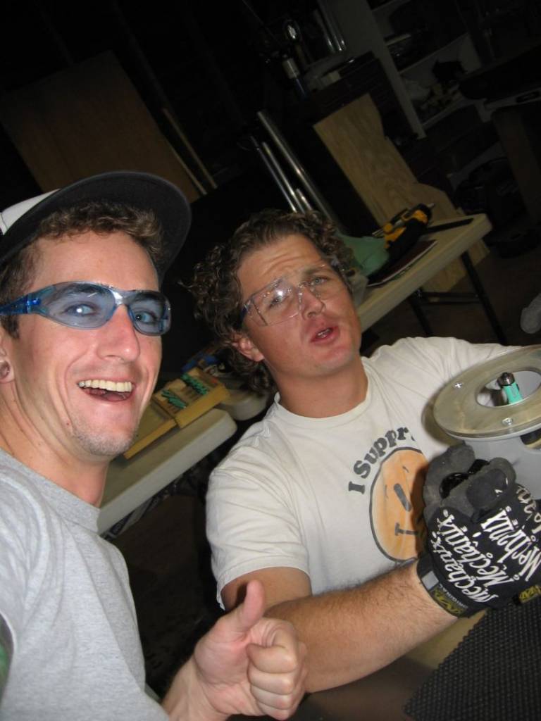
So we made the instrument panel last thuursday and I stuffed the gagues in today. Here's how it went.
1 - After taking measurements for box dimensions, make a template and test with cardboard. Then trace cardboard template onto plywood and cut out with jig saw or band saw.
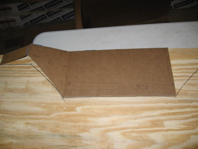
2 - Using the mystical powers of double-sided tape, attach 1/8" ABS to said template.
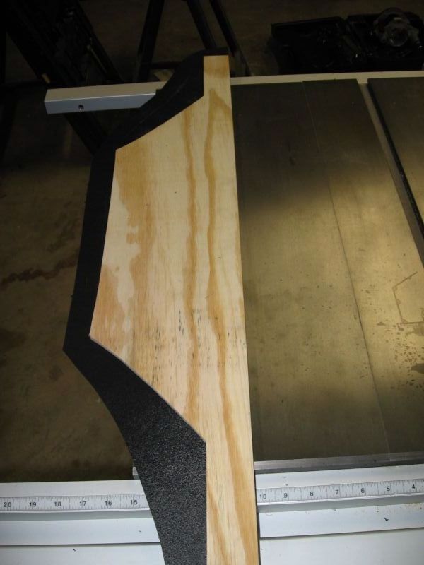
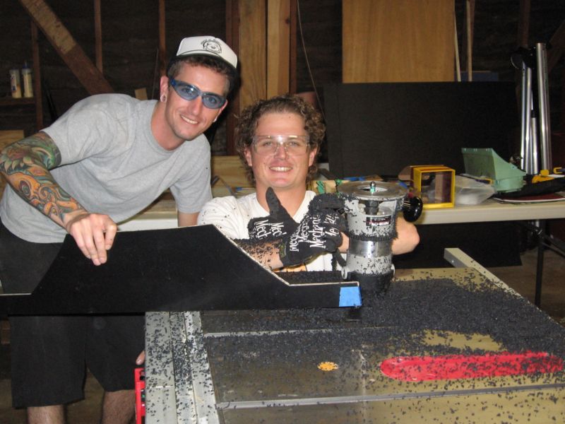
3 - Using a router with a flush trim bit and guide bearing, set router depth to follow plywood template and cut out ABS part. NOTE: You really should use a router table. However, since I don't have one yet, I firmly held the head of the router against the cast iron top of my table saw while my brother guided the part across the face. This is DANGEROUS. If you are not comfortable using a router, and even if you are, this is not a recommended "technique". Neverhteless, it worked like a charm for our purposes:
Before:
After:
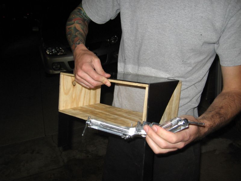
4 - Unfortunatley, I didn't get any pictures of the bending process, but basically with a heat gun (not a dryer, a heat gun) and buck (template around which to bend the plastic) heat up the edges for a cuple minutes and the piece will almost just fall into shape around the buck.
Here's what it looks like mid process or so:
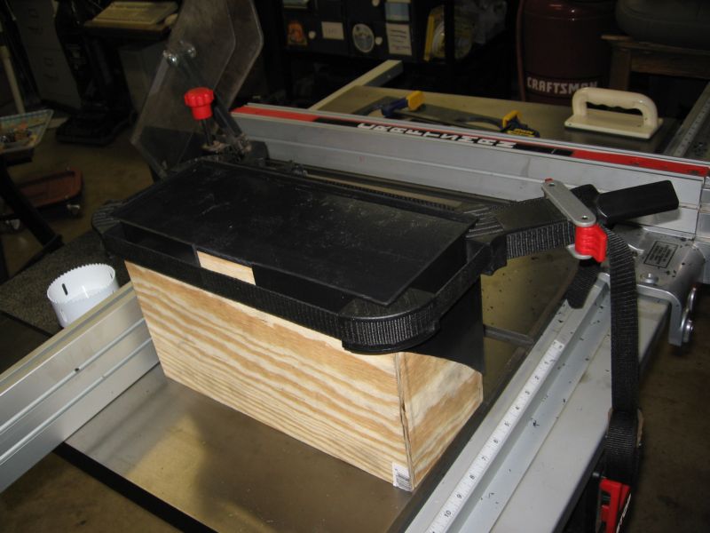
5 - Test fit the 1/4" ABS back plate into the box
6 - Protoype location of gauges.
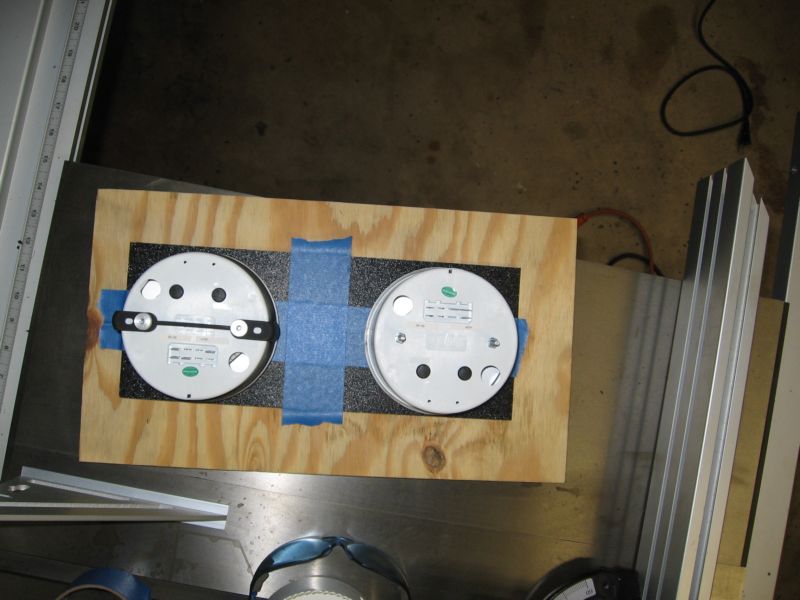
7 - Mark and cut holes for gauges and indicators.
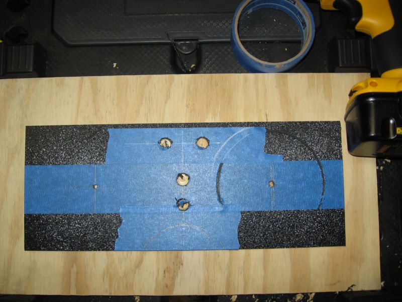
8 - Clamp backplate into box around buck and using Weldon 4 glue, apply to seam.
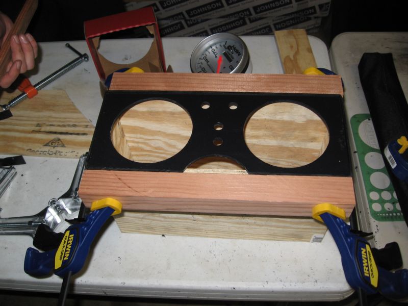
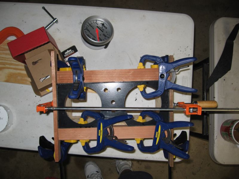
9 - Fasten gauges into openings.
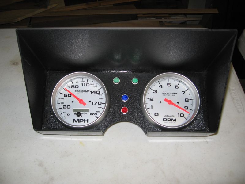
It's a little ghetto, but very tough and durable, certainly good enough for a couple years until I get to the interior. If it really starts to bug me, I can take this box panel and have it made out of sheet metal easily. |
|
|

|
 02-11-2007, 09:52 PM
|
#8
|
|
I, Vettezuki
Join Date: Feb 2006
Posts: 14,754
|
 Master Cylinder
Finally the the master cylinder is sorted out and installed. It took longer than I had hoped but but it's a solid installation.
Here's the MC. Note the 9/16" Heim jointed end that connects to the pedal. I had to cut the rod short and turn it down a bit to thread (it's an odd size) and put a stud for connecting the heim jointed end. From the cap of the MC to the center of the eye in the joint is about 6". Also, the hydraulic line is from McLeod. They have a 22" line with the correct GM OEM fitting for the slave and an AN-4 for the other end. The weird thing is the tap on the MC; it was a M12X1.0, which is a little odd and getting an AN -4 <-> M12x1.0 took a little while as well.
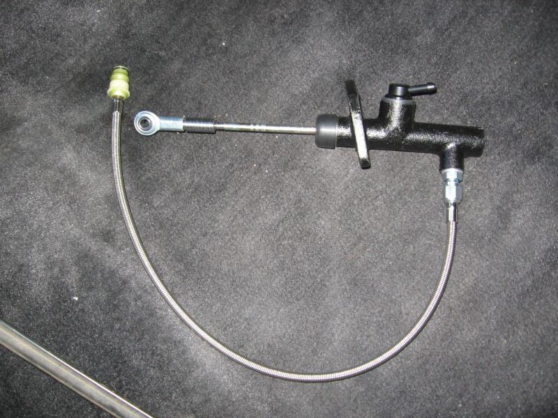
Installed from the inside. We drilled holes through the firewall and put bolts from the inside to act like studs. Otherwise, the truck master bolts up directly to the C3 firewall. NOTE: It seems the truck MC is an 11/16 bore and the slave is really designed to take a 3/4 bore. however, according to McLeod, as long as the stroke is about 1", it will move enough fluid to disengage the clutch.

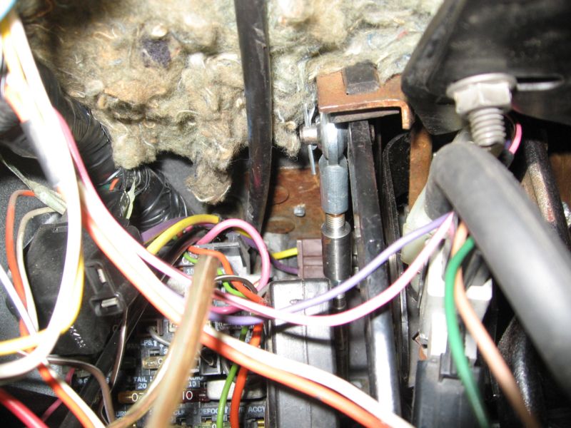
From inside the cabin. Here you can clearly see the heim jointed end connected to the clutch pedal. It is a good firm connection.
 |
|
|

|
 02-11-2007, 09:59 PM
|
#9
|
|
I, Vettezuki
Join Date: Feb 2006
Posts: 14,754
|
 It Continues
While not complete there has been considerable progress.
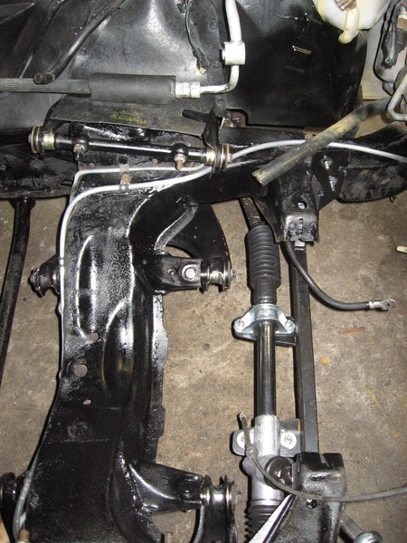
Let's begin with the Flaming River rack. As some of ya'lls might know, I decided to go with the FR bolt-in manual rack to replace my somewhat tired and not so accurate stock steering box. All in all it went in without too much hassle and came out looking something like the following:
View from passenger side:
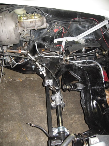
View from driver side:
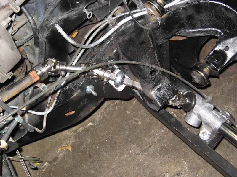
Close up view of linkage:
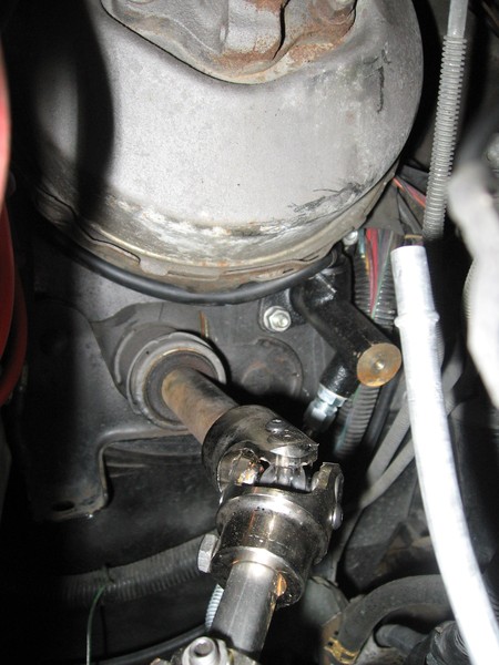
Steering input coming through firewall. You can also see the clutch MC:
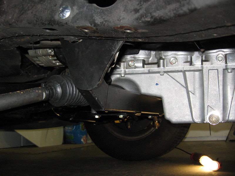
So it was all cool until the motor got slipped in. Ruh-roh. It seems FR designed the rack to work with a GenI and the F-Body pan on a GenIII just slightly touched the cradle for the rack. It will have to be pulled and modified with a slight notch and reinforcement. I've brought this to the attention of FR and they say they'll take a look at the issue. For those considering this rack with a GenIII in a C3, know that you'll have to modify the cradle, or wait until FR provides an updated design.
In the following pictures you can see how the modified heater pipes coming out of the water pump just barely clear the stock control arm:
One of the few, and frankly unsuspected get lucky moments was when we discovered that the stock drive shaft from the 82' works as is with the GenIII and T56 when using the Vette Works motor mount adapters and the stock Dana 44 rear-end. Since I hope to be putting *only* about 400HP to the ground the stock shaft and (rebuilt) rear end should be just fine.
One of the many, and frankly unsuspected get unlucky moments was when I realized my mechanic was right when he said Painless Wiring should be called Pain in the Ass Wiring. Run lengths to sensors were crap for this installation. You'd have to practically undue and re-bundle the harness. I thought it included wiring for fan control, but nope. Also, the fact it contained all the hookups for a manual and an automatic made it even messier. Yet another example of where trying to be all things to all people just doesn't work. So I returned it to our good friends at Summit and got a more purpose built harness from Speed Scene Wiring. With them you can talk about your application and they'll customize lengths. It also includes fan control with the GM OEM connectors, reverse lockout, backup lights, and only the trans sensors you need for your application. The stupid part is the total cost is virtually the same as the Painless. I've decided to go ahead and pull the stock ECM and harness completely and install the GenIII ECM in the stock location. This should go a great deal towards making a very clean install once it's all done.
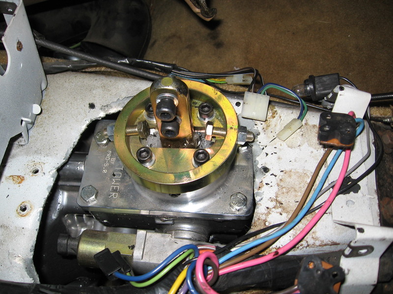
The Pro5 shifter came up in about the right place, but is pretty big, so we'll need to do a bit of modification to the trans tunnel to get it to come up nicely. And of course, we'll need an offset to get it to come out of the right place on the plate.
Oh yeah, the engine is in. We should be ready for the first fire up in about a month. Assuming I can get a tune and (gulp) pass the California engine swap referee I plan on taking it to Super Chevy in March; held this year at beautiful Fontana Speedway.
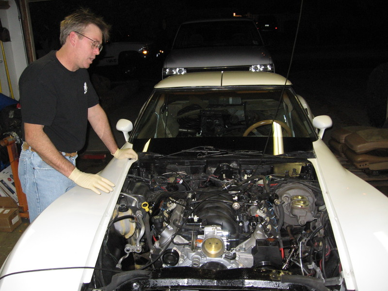
My mechanic/installer (ls1z28) is in the picture. I was very fortunate to find a guy who is patient and dedicated to doing things the right way for durable use, clean appearance and complete functionality.
Last edited by Vettezuki : 02-16-2007 at 02:48 AM.
|
|
|

|
 03-04-2007, 11:29 PM
|
#10
|
|
Senior Member
Join Date: Jan 2007
Posts: 325
|
Awesome!
I'm adding this line to pass the 10 character limit for posts lol.
|
|
|

|
 Posting Rules
|
You may not post new threads
You may not post replies
You may not post attachments
You may not edit your posts
HTML code is Off
|
|
|
|
